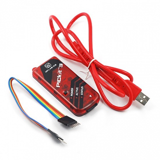


PICkit3 Debugger Programmer Emulator Controller Development
Microchip's PICkit™ 3 In-Circuit Debugger/Programmer uses in-circuit debugging logic incorporated into each chip with Flash memory to provide a low-cost hardware debugger and programmer. In-circuit debugging offers these benefits: Low cost. Minimum of additional hardware needed for debug.
₹ 2,399 ₹3,999
3,999


The PICkit 3 is a popular in-circuit debugger and programmer designed by Microchip Technology for use with their PIC microcontrollers. It offers a range of features for programming and debugging PIC microcontrollers and is commonly used in both development and educational settings.
Key Features:
-
Programming and Debugging:
- In-Circuit Debugging: Allows developers to debug their code directly on the target PIC microcontroller. It supports breakpoints, single-stepping, and variable monitoring.
- In-Circuit Programming: Can program the PIC microcontroller directly in the circuit, eliminating the need to remove the chip from the board.
-
Supported Devices:
- Microcontrollers: Compatible with a wide range of Microchip PIC microcontrollers, including PIC10, PIC12, PIC16, PIC18, PIC24, and dsPIC families. Compatibility varies depending on the version of the PICkit 3 firmware and software.
-
Connectivity:
- Interface: Connects to the target microcontroller via a 6-pin or 5-pin ICSP (In-Circuit Serial Programming) connector.
- Computer Interface: Connects to a PC via USB, allowing for programming and debugging through Microchip’s software tools.
-
Software Support:
- MPLAB X IDE: Works seamlessly with MPLAB X Integrated Development Environment (IDE), which provides tools for writing, compiling, and debugging code for PIC microcontrollers.
- MPLAB IPE (Integrated Programming Environment): Provides a simplified interface for programming PIC microcontrollers.
-
Power Supply:
- Power Source: The PICkit 3 is powered through the USB connection to the computer. It can also provide power to the target circuit if required, depending on the configuration.
-
LED Indicators:
- Status LEDs: The device includes LEDs that indicate power status, communication with the PC, and programming/debugging status.
Components and Connections:
-
PICkit 3 Unit:
- USB Connector: For connecting to a PC.
- ICSP Connector: A 6-pin or 5-pin connector used to interface with the target PIC microcontroller.
-
Target Microcontroller:
- ICSP Pins: The target microcontroller is connected to the PICkit 3 via the ICSP pins, which include VPP (Programming Voltage), VDD (Power), GND (Ground), PGD (Data), and PGC (Clock).
-
Software:
- MPLAB X IDE: Provides an environment for code development, debugging, and programming.
- MPLAB IPE: A simplified tool for direct programming without the need for a full IDE.
How to Use the PICkit 3:
-
Setup:
- Connect the PICkit 3: Plug the PICkit 3 into a USB port on your computer.
- Connect to Target: Attach the ICSP connector to the target microcontroller's programming header.
-
Software Installation:
- Install MPLAB X IDE or MPLAB IPE: Download and install the appropriate software from the Microchip website.
-
Programming:
- Open MPLAB X IDE or MPLAB IPE: Load your project or hex file.
- Configure Device: Select the target PIC microcontroller from the software’s device list.
- Program the Microcontroller: Use the software to program the microcontroller with your compiled code.
-
Debugging:
- Set Breakpoints and Debug: Use the MPLAB X IDE to set breakpoints, step through code, and monitor variables for debugging purposes.

// Define the analog pin where the Sharp sensor is connected
#define SHARP_SENSOR_PIN A0
void setup() {
// Start serial communication for debugging
Serial.begin(9600);
}
void loop() {
// Read the raw analog value from the Sharp sensor (0 to 1023)
int sensorValue = analogRead(SHARP_SENSOR_PIN);
// Convert the sensor value to voltage (0 to 5V)
float voltage = sensorValue * (5.0 / 1023.0);
// Calculate the distance in cm (using the Sharp sensor's formula)
// For GP2Y0A21YK0F, the distance is calculated as:
// Distance = (27.86 * pow(sensorValue, -1.10))
// This is an empirical formula based on datasheet values
// If using a different sensor, adjust the formula accordingly.
float distance = (27.86 * pow(sensorValue, -1.10));
// Print the raw sensor value, voltage, and calculated distance
Serial.print("Sensor Value: ");
Serial.print(sensorValue);
Serial.print(" Voltage: ");
Serial.print(voltage);
Serial.print("V Distance: ");
Serial.print(distance);
Serial.println(" cm");
// Add a delay for better readability of output
delay(500);
}
0 Reviews For this Product
Related Products


.jpg&width=225&quality=80)
