


MCP2515 CAN Module TJA1050 Receiver SPI 51 Single Chip Program Routine Arduino
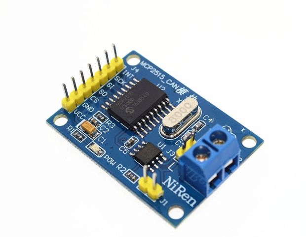
The MCP2515 CAN Bus Module is a stand-alone Controller Area Network (CAN) controller that implements the CAN 2.0B protocol:
₹ 109 ₹149
149


To interface the MCP2515 CAN Module (with the TJA1050 CAN transceiver) with an Arduino using the SPI (Serial Peripheral Interface) communication protocol, you'll need to follow these steps:
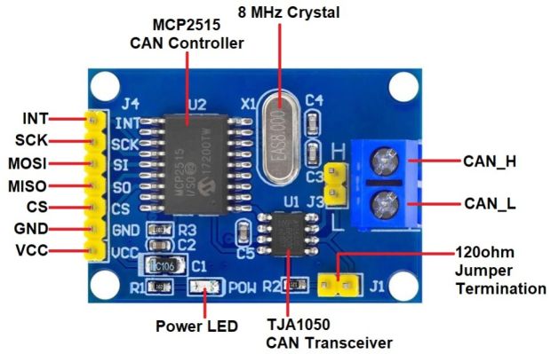
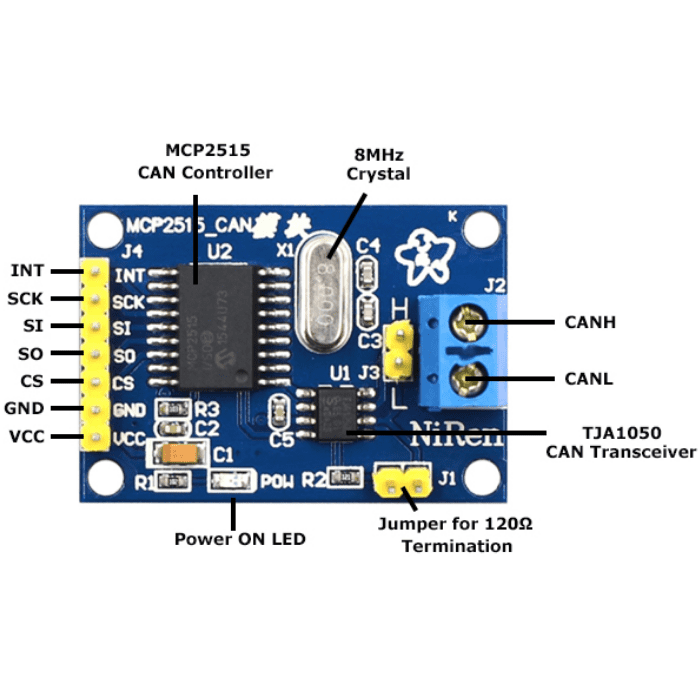
The MCP2515 is a stand-alone CAN controller that communicates with microcontrollers (like the Arduino) via SPI. The TJA1050 transceiver is used to interface the controller to the physical CAN bus.
Hardware Setup:
Components:
- MCP2515 CAN Module with TJA1050 transceiver.
- Arduino (e.g., Arduino Uno, Arduino Mega, etc.).
- Jumper wires for connections.
Wiring:
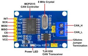
The MCP2515 module connects to the Arduino through SPI. The pinout for the MCP2515 module generally looks like this:
| MCP2515 Pin | Arduino Pin |
|---|---|
| VCC | 5V (or 3.3V depending on the module) |
| GND | GND |
| CS (Chip Select) | Pin 10 (or any other digital pin you configure) |
| SCK (Clock) | Pin 13 (SCK) |
| SI (MOSI) | Pin 11 (MOSI) |
| SO (MISO) | Pin 12 (MISO) |
| INT (Interrupt) | Pin 2 (or any other digital pin you configure) |
Ensure that your MCP2515 module operates at the correct voltage (either 5V or 3.3V) according to the specifications of the module you're using.
Arduino Code (Program Routine):
To use the MCP2515 CAN Module with Arduino, you can use the MCP2515 Arduino Library, which simplifies the interface between the Arduino and the CAN controller. This library allows you to set up the CAN bus communication, send and receive messages, and configure the MCP2515.
-
Install the MCP2515 Library:
- Open Arduino IDE.
- Go to Sketch → Include Library → Manage Libraries.
- In the Library Manager, search for "MCP2515" and install the library by "flexible" or any compatible library.
-
Code Example to Read and Write CAN Messages:
Here is an example program for initializing the MCP2515 CAN Module and reading messages from the CAN bus using SPI.
#include
#include

// Pin definitions
const int SPI_CS_PIN = 10; // Change to your CS pin if needed
const int CAN_INT_PIN = 2; // Interrupt pin for CAN module (can be any digital pin)

MCP2515 mcp2515(SPI_CS_PIN);

// Define a CAN message object
struct can_frame canMsg;

void setup() {
  // Start Serial Communication for debugging
  Serial.begin(115200);
  while (!Serial);

  // Initialize the MCP2515 module
  if (mcp2515.begin(MCP2515::MODE_NORMAL)) {
    Serial.println("MCP2515 initialized in Normal mode");
  } else {
    Serial.println("MCP2515 initialization failed");
    while (1);
  }

  // Set the MCP2515 to listen for CAN messages
  pinMode(CAN_INT_PIN, INPUT);
  attachInterrupt(digitalPinToInterrupt(CAN_INT_PIN), readCANMessage, FALLING);
}

void loop() {
  // Main loop doesn't need to do anything for now
  // The interrupt will handle CAN message reception
}

void readCANMessage() {
  // Check if a message is available
  if (mcp2515.readMessage(&canMsg)) {
    // Print the received CAN message ID and data
    Serial.print("Message received with ID: ");
    Serial.println(canMsg.can_id, HEX);
    Serial.print("Data: ");
    for (int i = 0; i < canMsg.can_dlc; i++) {
      Serial.print(canMsg.data[i], HEX);
      Serial.print(" ");
    }
    Serial.println();
  }
}
Explanation:
-
Library and Pin Definitions:
- The program uses the
SPIandmcp2515libraries. You include the libraries at the beginning of the code. - Pin 10 is set as the Chip Select (CS) pin, and pin 2 is used for CAN interrupt handling (this can be changed depending on your setup).
- The program uses the
-
MCP2515 Initialization:
mcp2515.begin(MCP2515::MODE_NORMAL)initializes the MCP2515 in Normal Mode, meaning it will listen to the CAN bus and process incoming messages. The module will start receiving data if any CAN message is sent over the bus.
-
Interrupt Handling:
- The CAN interrupt pin (INT) is configured to detect falling edges (when the CAN bus sends a message). When a message is received, the
readCANMessagefunction is called to retrieve and print the message.
- The CAN interrupt pin (INT) is configured to detect falling edges (when the CAN bus sends a message). When a message is received, the
-
Reading and Printing Messages:
- The
readMessage()function is used to read the CAN frame from the MCP2515. After the message is read, thecan_idand the data bytes are printed to the serial monitor.
- The
Sending CAN Messages:
To send a message over the CAN bus, you can use the sendMessage function. Below is an example of how to send a CAN message:
void sendCANMessage() {
  canMsg.can_id  = 0x123; // CAN ID
  canMsg.can_dlc = 8; // Data length (max 8 bytes)

  // Data to send
  canMsg.data[0] = 0x01;
  canMsg.data[1] = 0x02;
  canMsg.data[2] = 0x03;
  canMsg.data[3] = 0x04;
  canMsg.data[4] = 0x05;
  canMsg.data[5] = 0x06;
  canMsg.data[6] = 0x07;
  canMsg.data[7] = 0x08;

  // Send the message
  if (mcp2515.sendMessage(&canMsg)) {
    Serial.println("Message sent successfully!");
  } else {
    Serial.println("Message sending failed.");
  }
}

void loop() {
  sendCANMessage();
  delay(1000); // Send message every 1 second
}
Explanation of the Sending Routine:
- CAN Message Structure:
- The
canMsgstructure defines the CAN message, which includes the ID and data (up to 8 bytes). - You assign a CAN ID (like
0x123) and specify the data to send (up to 8 bytes). - Use the
sendMessage()function to send the message over the CAN bus.
- The
Important Notes:
- Ensure that the MCP2515 module is powered correctly (typically 5V).
- The CAN bus must have terminators at each end to ensure stable communication.
- If you're working with multiple CAN nodes, each node must have a unique CAN ID to avoid conflicts.
Conclusion:
By following the steps above, you can successfully interface the MCP2515 CAN Module with an Arduino using SPI. This setup allows you to read and send CAN messages on the CAN bus, enabling you to build applications like vehicle communication systems, industrial automation, robotics, and embedded systems.
0 Reviews For this Product
Related Products


.jpg&width=225&quality=80)
