![](https://electroboat.in/uploads/media/2024/600x600.jpeg)
![](https://electroboat.in/media/image?path=uploads/media/2024/images_(9).jpeg&width=620&quality=80)
![](https://electroboat.in/media/image?path=uploads/media/2024/images_(10).jpeg&width=620&quality=80)
![](https://electroboat.in/media/image?path=uploads/media/2024/600x600.jpeg&width=175&quality=80)
![](https://electroboat.in/media/image?path=uploads/media/2024/images_(9).jpeg&width=172&quality=80)
![](https://electroboat.in/media/image?path=uploads/media/2024/images_(10).jpeg&width=172&quality=80)
![](https://electroboat.in/media/image?path=uploads/media/2024/600x600.jpeg&width=300&quality=80)
![](https://electroboat.in/media/image?path=uploads/media/2024/images_(9).jpeg&width=300&quality=80)
![](https://electroboat.in/media/image?path=uploads/media/2024/images_(10).jpeg&width=300&quality=80)
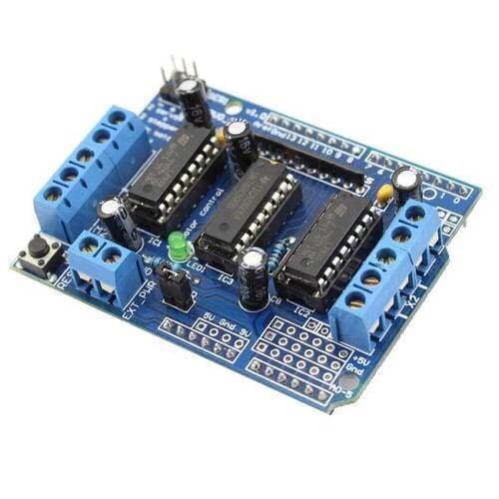
L293D MOTOR DRIVER MODULE
L293D Motor Driver Module is a medium power motor driver perfect for driving DC Motors and Stepper Motors. It uses the popular L293 motor driver IC. It can drive 4 DC motors on and off, or drive 2 DC motors with directional and speed control.
₹ 119 ₹199
199
![](https://electroboat.in/assets/front_end/classic/images/cod_logo.png)
![](https://electroboat.in/assets/front_end/classic/images/cancelable.png)
![](https://electroboat.in/assets/front_end/classic/images/returnable.png)
Made In : | India |
Add FAQ
The L293D is a popular integrated circuit (IC) used as a motor driver to control the direction and speed of DC motors and stepper motors in various electronic projects. It is widely used in robotics, automation, and other applications that require precise motor control.
L293D Motor Driver Overview:
1. Key Features:
-
Dual H-Bridge:
- Contains two H-bridge circuits that can independently drive two DC motors or one stepper motor.
-
Voltage Range:
- Input Voltage Range: Typically 4.5V to 36V DC.
- Output Voltage Range: Matches the input voltage, up to 36V.
-
Current Capability:
- Continuous Output Current: Up to 600mA per channel.
- Peak Output Current: Up to 1.2A per channel for brief periods.
-
Thermal Protection:
- Includes thermal shutdown and overload protection to prevent damage due to overheating or excessive current.
-
Built-in Diodes:
- Internal diodes protect against back electromotive force (back EMF) generated by motors.
2. Pin Configuration:
The L293D typically comes in a 16-pin dual in-line package (DIP). The pin configuration is as follows:
-
Pin 1 (Enable 1,2): Enables the H-bridge for motor 1. Connecting this pin to a high logic level (e.g., 5V) allows motor 1 to be controlled.
-
Pin 2 (Input 1): Controls the direction of motor 1. A high logic level turns the motor in one direction, and a low logic level turns it in the opposite direction.
-
Pin 3 (Output 1): Connects to one terminal of motor 1.
-
Pin 4 (GND): Ground pin. Connects to the ground of the power supply.
-
Pin 5 (Output 2): Connects to the other terminal of motor 1.
-
Pin 6 (Input 2): Controls the direction of motor 1, similar to pin 2. Provides the opposite direction to the motor.
-
Pin 7 (VCC2): Connects to the power supply for the motor. This can be different from the logic voltage (VCC1).
-
Pin 8 (VCC1): Connects to the logic power supply (e.g., 5V for the control logic).
-
Pin 9 (Enable 3,4): Enables the H-bridge for motor 2. Connecting this pin to a high logic level allows motor 2 to be controlled.
-
Pin 10 (Input 3): Controls the direction of motor 2. A high logic level turns the motor in one direction, and a low logic level turns it in the opposite direction.
-
Pin 11 (Output 3): Connects to one terminal of motor 2.
-
Pin 12 (GND): Ground pin. Connects to the ground of the power supply.
-
Pin 13 (Output 4): Connects to the other terminal of motor 2.
-
Pin 14 (Input 4): Controls the direction of motor 2, similar to pin 10. Provides the opposite direction to the motor.
-
Pin 15 (VCC2): Connects to the power supply for the motor, similar to pin 7.
-
Pin 16 (VCC1): Connects to the logic power supply, similar to pin 8.
3. Working Principle:
-
H-Bridge Operation:
- Each H-bridge within the L293D controls the direction of current flow through the motor. By activating different combinations of the input pins, the motor's direction and speed can be controlled.
-
Motor Direction:
- By setting the input pins (Input 1 and Input 2 for Motor 1; Input 3 and Input 4 for Motor 2) to high or low logic levels, you can control the direction of rotation of the motors.
-
Speed Control:
- Speed can be controlled using Pulse Width Modulation (PWM) applied to the enable pins. By varying the duty cycle of the PWM signal, the effective voltage applied to the motor can be adjusted, thereby controlling the speed.
4. Applications:
-
Robotics:
- Used in robotic systems to drive DC motors for movement, steering, and other functions.
-
Automation:
- Controls motors in automated systems for opening and closing mechanisms, conveyor belts, and more.
-
DIY Projects:
- Commonly used in hobbyist projects to control small motors, such as in remote-controlled cars or simple mechanical systems.
5. Advantages:
-
Ease of Use:
- Simplifies motor control by integrating multiple components into a single IC.
-
Protection Features:
- Includes thermal shutdown and internal diodes for protection.
-
Versatility:
- Can control both DC motors and stepper motors, making it suitable for a range of applications.
6. Limitations:
-
Current Limitation:
- Maximum continuous current of 600mA per channel may not be sufficient for high-power motors.
-
Heat Dissipation:
- High current operation may require additional heat sinking to prevent overheating.
Example Use Case:
Robotic Car:
- In a robotic car, the L293D can be used to control two DC motors for driving the wheels. By setting the input pins, the car's direction and speed can be controlled via PWM signals applied to the enable pins.
Summary:
The L293D motor driver IC is a versatile and reliable solution for controlling DC motors and stepper motors. With its dual H-bridge configuration, built-in protection features, and ease of integration, it is well-suited for various applications in robotics, automation, and DIY projects. Its ability to handle moderate current loads and control motor direction and speed makes it a popular choice for motor control tasks.
![](https://4.bp.blogspot.com/-wvFouPGkPD8/V83Jm8l_RYI/AAAAAAAAFNk/1yo8_A2kz9AoBA_Ob43IfM_K7YYnc6iJQCLcB/s1600/wiring12.png)
0 Reviews For this Product
![](https://electroboat.in/uploads/seller/electroboat_logo3.jpeg)