
.jpeg&width=620&quality=80)


.jpeg&width=172&quality=80)


.jpeg&width=300&quality=80)
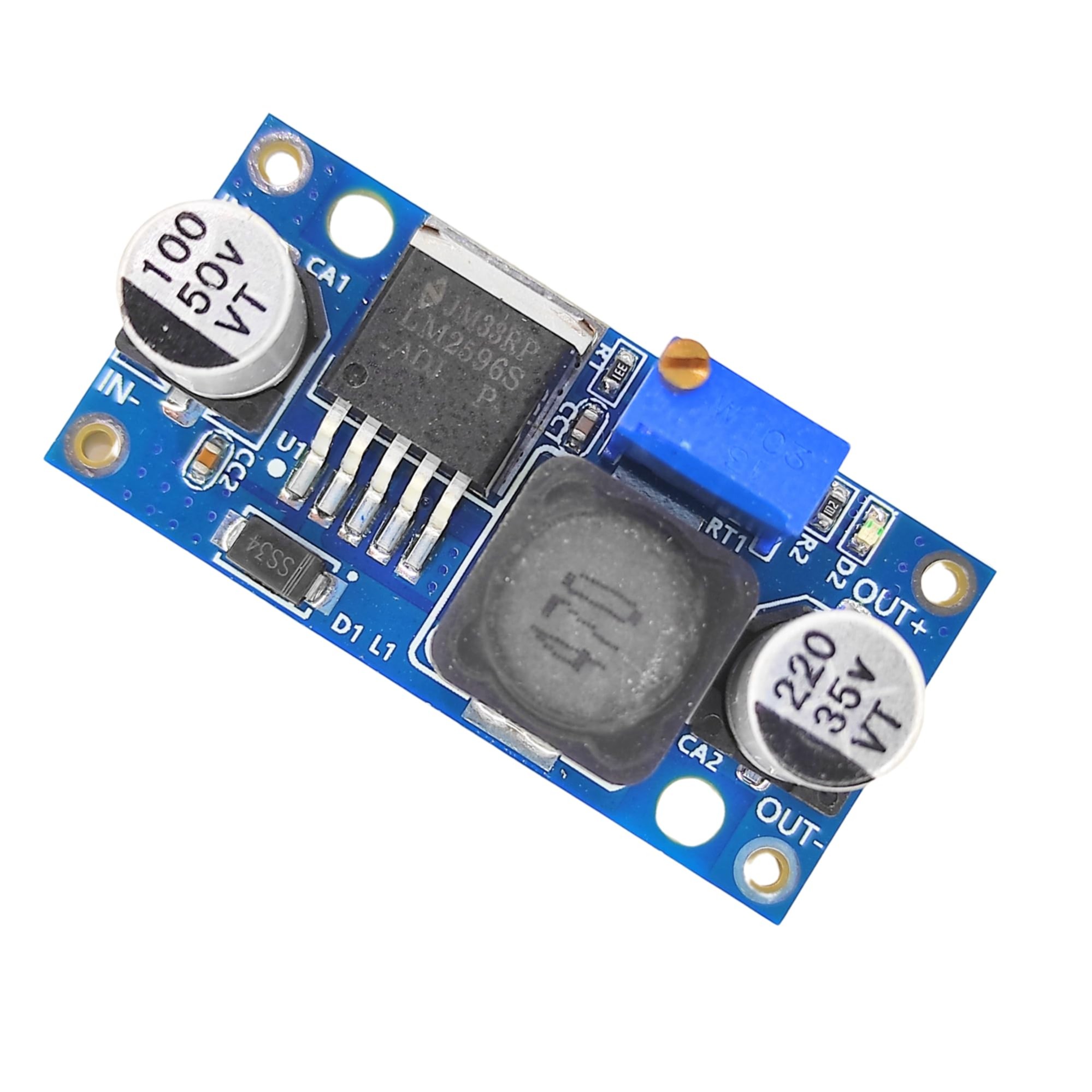
DC TO DC BUCK CONVERTOR
A buck converter or step-down converter is a DC-to-DC converter which decreases voltage, while increasing current, from its input (supply) to its output (load). It is a class of switched-mode power supply.
₹ 62 ₹99
99


| Made In : | India |
Add FAQ
A DC-DC buck converter is a type of switch-mode power supply that steps down a higher DC voltage to a lower DC voltage with high efficiency. It is commonly used in various electronic devices and systems to provide a stable voltage supply from a higher voltage source. Here’s a detailed overview of DC-DC buck converters:
DC-DC Buck Converter Overview:
1. Key Features:
-
Voltage Conversion:
- Steps down a higher DC voltage to a lower DC voltage. For example, it can convert 12V DC to 5V DC.
-
High Efficiency:
- Typically achieves high efficiency (90% or more), minimizing energy loss compared to linear regulators.
-
Adjustable Output:
- Many buck converters allow adjustment of the output voltage via external feedback or control mechanisms.
-
Stable Output:
- Provides a stable and regulated output voltage, even when the input voltage or load conditions vary.
2. Working Principle:
-
Switching Operation:
- The buck converter uses a switching element (usually a MOSFET) that rapidly turns on and off. This switching action converts the input voltage into a series of pulses.
-
Inductor and Capacitor:
- An inductor and capacitor are used to filter the switching pulses and smooth the output voltage. The inductor stores energy during the ON phase and releases it during the OFF phase.
-
Feedback Mechanism:
- A feedback loop compares the output voltage with a reference voltage and adjusts the duty cycle of the switching element to maintain a constant output voltage.
-
Duty Cycle:
- The ratio of the ON time to the total switching period determines the output voltage. The longer the ON time, the higher the output voltage.
3. Circuit Components:
-
Switching Element:
- MOSFET or Transistor: Acts as a switch to control the flow of current.
-
Inductor:
- Stores energy when the switch is ON and releases it when the switch is OFF, smoothing the current.
-
Capacitor:
- Filters the output voltage to reduce ripple and stabilize the output.
-
Diode:
- Provides a path for current when the switching element is OFF. A Schottky diode is commonly used due to its low forward voltage drop and fast recovery time.
-
Feedback Network:
- Comprises resistors or an internal reference to regulate the output voltage.
4. Efficiency and Performance:
-
Efficiency:
- Buck converters are highly efficient, typically around 85-95%, due to their switching nature and minimal power dissipation.
-
Switching Frequency:
- The frequency of switching affects the size of the inductor and capacitor. Higher frequencies allow for smaller components but may generate more electromagnetic interference (EMI).
-
Thermal Management:
- Effective heat dissipation is necessary to prevent overheating, especially in high-power applications.
5. Applications:
-
Power Supplies:
- Used in power supplies for electronic devices to provide different voltage levels from a single power source.
-
Battery-Powered Devices:
- Efficiently converts battery voltage to the required levels for powering various components.
-
Computers and Electronics:
- Employed in computer motherboards, graphics cards, and other electronics requiring stable power conversion.
-
Automotive:
- Provides regulated power to automotive electronics from the vehicle’s main battery.
6. Advantages:
-
High Efficiency:
- Reduces power loss and extends battery life in portable devices.
-
Compact Size:
- Smaller components and less heat generation compared to linear regulators.
-
Stable Output:
- Maintains a constant output voltage despite variations in input voltage or load.
7. Limitations:
-
Complexity:
- More complex than linear regulators due to the need for additional components and control circuitry.
-
EMI:
- Switching action can generate electromagnetic interference (EMI) that may need to be managed.
-
Cost:
- Generally more expensive than linear regulators, though the cost is justified by the efficiency gains.
Example Use Case:
Power Supply for Microcontroller:
- A buck converter can step down a 12V input to 5V to power a microcontroller. This provides efficient power conversion, reducing heat and extending battery life compared to a linear regulator.
Summary:
A DC-DC buck converter is an efficient power supply solution for stepping down a higher DC voltage to a lower DC voltage. It uses a switching element, inductor, capacitor, and feedback mechanism to provide a stable output voltage with high efficiency. Buck converters are widely used in power supplies, battery-powered devices, and electronic systems requiring regulated voltage. Their advantages in efficiency and compact size make them a popular choice for various applications, despite their complexity and potential EMI concerns.
import RPi.GPIO as GPIO
import time
# Set the GPIO mode to BCM (Broadcom pin-numbering scheme)
GPIO.setmode(GPIO.BCM)
# Define the PWM pin (GPIO 18 is used for PWM)
PWM_PIN = 18
# Set the GPIO pin as an output
GPIO.setup(PWM_PIN, GPIO.OUT)
# Set up PWM with 1 kHz frequency (this can be adjusted based on your requirements)
pwm = GPIO.PWM(PWM_PIN, 1000)
# Start PWM with 0% duty cycle (fully off)
pwm.start(0)
def set_output_voltage(desired_voltage):
"""
Function to set the desired output voltage.
The formula for duty cycle adjustment depends on the input voltage and output voltage.
Here, we assume a simple relationship: Duty Cycle (%) = (Vout / Vin) * 100
"""
input_voltage = 12 # Input voltage, adjust as needed (e.g., 12V)
if desired_voltage > input_voltage:
print("Error: Desired output
0 Reviews For this Product


.jpg&width=225&quality=80)
