5.jpeg&width=620&quality=80)


5.jpeg&width=172&quality=80)


5.jpeg&width=300&quality=80)

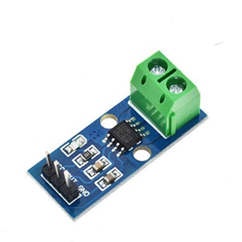
ACS335 current sensor Module
The ACS335 is a current sensor module typically used for measuring AC and DC currents. It operates on the principle of Hall effect sensing and provides an output voltage proportional to the current flowing through the conductor.
₹ 413 ₹513
513


The ACS335 Current Sensor Module is a device used for measuring AC (Alternating Current) in a circuit. It provides a means to sense the amount of current flowing through a conductor and convert this into a proportional electrical signal, which can be processed by a microcontroller (like an Arduino or Raspberry Pi). The ACS335 is based on the ACS330 series of current sensors developed by Allegro Microsystems, which uses a hall-effect sensor for non-contact current measurement.
Key Features of the ACS335 Current Sensor Module:
-
Hall Effect Sensing:
- The ACS335 sensor uses Hall effect technology to measure the magnetic field generated by the current flowing through a conductor. This allows it to measure the current without directly contacting the conductor, making it electrically isolated and safe for use in high-voltage applications.
-
Measurement Type:
- The module can measure AC (Alternating Current), with an output that is proportional to the average current.
-
Output Voltage:
- The ACS335 provides an analog output that varies in relation to the measured current. Typically, the output voltage is 0 to 5V (or another voltage range, depending on the specific version of the module), with the sensor’s output being proportional to the amount of current being measured.
-
Current Range:
- The module has a wide range of measurable currents. For example, it can measure currents in the range of 0 to 5A or 0 to 20A, depending on the specific model and its current sensing range.
- Some modules may have a different current sensing range, like 100A, 50A, or higher, depending on the need.
-
Accuracy and Resolution:
- The accuracy of the ACS335 module depends on its specific model but is generally sufficient for most basic current monitoring applications. The output resolution can also vary depending on the resolution of the ADC (Analog to Digital Converter) used in the microcontroller.
-
Linear Output:
- The module’s output is generally linear, meaning that the output voltage increases proportionally to the amount of current being measured. This is ideal for analog-to-digital conversion in microcontrollers, as you can directly correlate the voltage readings to the current.
-
Power Supply:
- The ACS335 typically operates with a 5V DC power supply (though some models may use 3.3V DC depending on the system), which is compatible with most microcontrollers like Arduino or Raspberry Pi.
-
Low Power Consumption:
- These sensors are designed to consume minimal power, which makes them suitable for battery-operated systems or low-power applications.
Pinout of the ACS335 Current Sensor Module:
The typical ACS335 sensor module has the following pins:
| Pin Name | Description |
|---|---|
| VCC | Power supply for the module (typically 5V or 3.3V). |
| GND | Ground connection. |
| OUT | Analog output (measured voltage proportional to the current). |
| IP+ | Input terminal for positive current flow. |
| IP- | Input terminal for negative current flow. |
| SENSE | Current sensing input (connected to the conductor being monitored). |
Working Principle:
-
Current Flow: The current flowing through a conductor generates a magnetic field. The ACS335 uses a Hall effect sensor to detect this magnetic field.
-
Magnetic Field Detection: The Hall effect sensor detects the magnetic field created by the current and converts this information into an analog voltage signal.
-
Output Voltage: The analog output signal is a voltage that corresponds to the amount of current flowing through the conductor. Typically, this is a linear relationship where the voltage increases as the current increases. For instance, the output voltage might range from 0V (for 0A) to 5V (for the maximum measurable current).
Example: Using the ACS335 Current Sensor with Arduino
Let’s consider an example where we use an ACS335 Current Sensor Module with an Arduino to measure the current.
Wiring the ACS335 Module to Arduino:
- VCC → Connect to 5V on Arduino.
- GND → Connect to GND on Arduino.
- OUT → Connect to an analog input pin (e.g., A0) on Arduino.
- IP+ and IP- → Connect to the circuit where you want to measure the current (for example, in series with a load).
Arduino Code to Read Current:
// Define the pin for reading the current sensor output
const int currentPin = A0;

// Variable to store the sensor reading
int sensorValue = 0;

// Variable to store the actual current in Amperes
float current = 0.0;

void setup() {
  // Start serial communication for debugging
  Serial.begin(9600);
}

void loop() {
  // Read the analog value from the current sensor
  sensorValue = analogRead(currentPin);

  // Convert the analog reading (0-1023) to a voltage (0-5V)
  float voltage = sensorValue * (5.0 / 1023.0);

  // Calculate the current based on the sensor’s output
  // Assuming the sensor's output voltage is 0V at 0A and 5V at max current (5A).
  // This is an example, and you need to adjust based on your sensor's datasheet.
  current = (voltage - 2.5) * 5;  // Linear equation: output voltage varies between 0-5V.

  // Print the current to the Serial Monitor
  Serial.print("Current: ");
  Serial.print(current, 3);  // Show the current value with 3 decimal places.
  Serial.println(" A");

  // Wait for a short period before taking the next reading
  delay(500);
}
Explanation of the Code:
-
Reading the Sensor:
- We use analogRead() to read the voltage from the sensor’s output pin. The Arduino’s ADC converts this analog signal to a value between 0 and 1023 (for 0-5V).
-
Converting to Voltage:
- We convert the sensor’s raw value into a voltage using the formula:
voltage = (sensorValue * (5.0 / 1023.0))
- We convert the sensor’s raw value into a voltage using the formula:
-
Calculating the Current:
- The ACS335 module's output is typically designed so that 2.5V corresponds to 0A of current. So, we subtract 2.5V from the measured voltage to center the output around 0V.
- Then, we multiply by a factor (in this case, 5) to calculate the actual current in Amperes.
- This factor (5) needs to be adjusted according to your sensor's calibration and range. For instance, if your sensor is designed for a maximum current of 5A, and its output voltage range is from 0V to 5V, the factor would be 5.
-
Displaying the Current:
- The calculated current is printed to the Serial Monitor for visualization.
Applications:
-
Energy Monitoring:
- Measure the power consumption of household appliances, electric motors, or other devices.
-
Battery Management Systems (BMS):
- Monitor the charging or discharging current of a battery to ensure safe operation.
-
Overcurrent Protection:
- Use the ACS335 to monitor current and trigger a relay or shutdown in case of excessive current (overload).
-
Solar Power Systems:
- Monitor the current output from solar panels to assess system performance.
-
Industrial Monitoring:
- Track currents in industrial machines and equipment to detect potential issues such as overloads or inefficiencies.
Conclusion:
The ACS335 Current Sensor Module is an excellent tool for measuring AC current in circuits. It provides a safe, non-contact method to monitor current flow and can be easily interfaced with a microcontroller like Arduino or Raspberry Pi. With its linear output and ease of use, it's ideal for energy monitoring, overcurrent protection, and many other applications in IoT and automation systems.
0 Reviews For this Product
Related Products


.jpg&width=225&quality=80)
