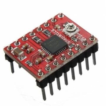


A4988 driver Stepper Motor Driver
The A4988 is a complete microstepping motor driver with built-in translator for easy operation
₹ 99 ₹149
149


The A4988 is a popular stepper motor driver integrated circuit (IC) designed for controlling bipolar stepper motors. It is commonly used in 3D printers, CNC machines, and other applications requiring precise control of stepper motors.
Key Features:
-
Microstepping Capability:
- Microstepping: The A4988 supports up to 16 microsteps per full step. This feature allows for smoother and more precise control of the stepper motor, improving performance and reducing vibration.
- Step Resolution: The IC supports full, half, quarter, eighth, and sixteenth-step modes.
-
Current Limiting:
- Adjustable Current Limit: The A4988 has an adjustable current limiting feature, which allows you to set the maximum current that the driver can supply to the motor. This helps to prevent overheating and damage to both the motor and driver.
-
Decay Modes:
- Decay Modes: The driver supports different decay modes (fast and slow decay) to optimize motor performance and minimize heating.
-
Thermal and Overcurrent Protection:
- Overtemperature Protection: The A4988 includes thermal shutdown to protect the driver from overheating.
- Overcurrent Protection: Includes built-in current limiting to prevent excessive current that could damage the driver or motor.
-
Interface:
- Control Pins: The A4988 provides several control pins for step and direction inputs, as well as microstepping selection.
- Enable Pin: Can disable the driver when not in use to save power and reduce heat.
-
Power Supply:
- Voltage Range: The A4988 operates with a supply voltage ranging from 8V to 35V.
- Current Capability: It can supply up to 2A per phase (depending on cooling and proper adjustment).
Pinout and Connections:
Here’s a typical pinout for the A4988 stepper motor driver:
- VMOT: Motor power supply (8V to 35V).
- GND: Ground connection.
- VDD: Logic power supply (typically 3.3V to 5V).
- GND (Logic): Ground for logic circuitry.
- STEP: Step signal input.
- DIR: Direction signal input.
- ENABLE: Enable pin to activate/deactivate the driver.
- MS1, MS2, MS3: Microstepping resolution control pins.
- RESET: Reset pin to restart the driver.
- SLEEP: Sleep pin to put the driver in a low-power state.
- OUT1A, OUT1B, OUT2A, OUT2B: Motor output connections (to the stepper motor).

// Pin Definitions
const int stepPin = 3; // Pin connected to the STEP pin of A4988
const int dirPin = 4; // Pin connected to the DIR pin of A4988
// Number of steps for a full rotation (depends on the motor and its specifications)
const int stepsPerRevolution = 200; // Adjust according to your stepper motor (e.g., 200 for 1.8° step angle)
void setup() {
// Set the STEP and DIR pins as output
pinMode(stepPin, OUTPUT);
pinMode(dirPin, OUTPUT);
// Start by rotating in one direction
digitalWrite(dirPin, HIGH); // Set the direction (HIGH or LOW)
}
void loop() {
// Rotate the stepper motor one full revolution
for (int step = 0; step < stepsPerRevolution; step++) {
// Create a pulse on the STEP pin to move the motor one step
digitalWrite(stepPin, HIGH);
delayMicroseconds(1000); // Adjust delay for speed control (lower value = faster rotation)
digitalWrite(stepPin, LOW);
delayMicroseconds(1000); // Adjust delay for speed control
}
// Pause for a moment after completing one revolution
delay(1000);
// Reverse the direction of rotation
digitalWrite(dirPin, LOW); // Reverse direction
// Rotate the stepper motor one full revolution in the opposite direction
for (int step = 0; step < stepsPerRevolution; step++) {
digitalWrite(stepPin, HIGH);
delayMicroseconds(1000); // Adjust delay for speed control
digitalWrite(stepPin, LOW);
delayMicroseconds(1000); // Adjust delay for speed control
}
// Pause before starting another cycle
delay(1000);
}
0 Reviews For this Product
Related Products


.jpg&width=225&quality=80)
