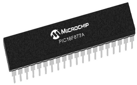


PIC 16f877A IC
It is a 40-pin 8-bit Microcontroller with 14kB of program memory. It does not have an internal oscillator but can work up to 20MHz with external oscillators. The controller has 8 ADC channels with 10-bit resolution and also supports PWM on 2 pins.
₹ 260 ₹350
350


| Made In : | India |
Add FAQ
The PIC16F877A is a widely used 8-bit microcontroller from Microchip Technology that belongs to the PIC16 family of microcontrollers. It is a popular choice for many embedded system projects due to its versatility, ease of use, and robust set of features, making it suitable for a wide variety of applications.
Key Features of the PIC16F877A:
-
Architecture:
- 8-bit RISC (Reduced Instruction Set Computing) architecture.
- Operates with a Harvard architecture: separate memory spaces for program code and data, enabling faster instruction execution.
-
Flash Memory:
- 14KB of Flash Program Memory for storing the firmware or program code.
- 368 Bytes of SRAM for storing data and variables during execution.
- 256 Bytes of EEPROM for non-volatile memory storage (ideal for saving settings or calibration data that should persist between power cycles).
-
Clock Speed:
- Operates at a maximum clock speed of 20 MHz, which translates to a maximum instruction cycle time of 200 ns. This allows for fairly high performance in many control applications.
-
Input/Output Pins:
- The PIC16F877A comes in a 40-pin package with 33 I/O pins. These I/O pins can be individually configured as either input or output, and they are used to interface with external components like sensors, switches, LEDs, etc.
-
Timers and Counters:
- It has 3 timers: Timer0, Timer1, and Timer2. These timers can be used for time-based operations such as delays, generating PWM signals, or as counters for external events.
- PWM (Pulse Width Modulation) capability for controlling devices like motors, LEDs, and other actuators.
-
Analog-to-Digital Converter (ADC):
- It has a 10-bit ADC with 8 channels, allowing it to read analog input signals (such as from sensors or voltage dividers) and convert them to digital signals for processing.
-
Communication Interfaces:
- USART (Universal Synchronous Asynchronous Receiver Transmitter) for serial communication (RS-232, UART) with other devices.
- SPI (Serial Peripheral Interface) and I2C (Inter-Integrated Circuit) interfaces for communication with other microcontrollers or external peripherals like sensors, memory chips, and displays.
-
Interrupts:
- Supports interrupts from multiple sources, including external pins, internal timers, and serial communication. Interrupts allow for responsive handling of real-time events.
-
Low Power Consumption:
- The PIC16F877A is designed for low power operation and has several power-saving modes, including a sleep mode, where the microcontroller can be put to low power consumption while waiting for an event or external interrupt.
-
Watchdog Timer:
- The watchdog timer helps in improving system reliability by automatically resetting the microcontroller in case of a system failure or crash.
-
On-chip Peripherals:
- The device integrates several on-chip peripherals like the Brown-Out Reset (BOR) circuit, Power-On Reset (POR), Low-Voltage Detection (LVD), and Internal Oscillator to improve system stability and reduce the need for external components.
-
Power Supply:
- The PIC16F877A operates on a 2.0V to 5.5V power supply, making it flexible for a variety of power sources (e.g., battery-powered systems or standard 5V systems).
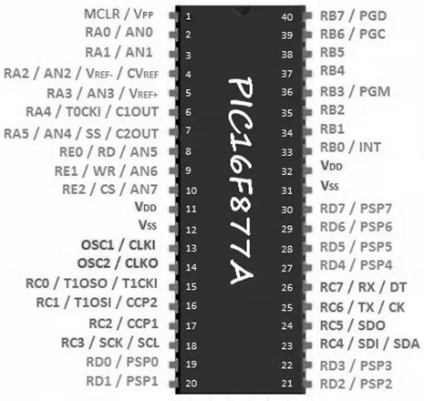
Pinout of the PIC16F877A:
- 40 pins in a DIP (Dual In-line Package) or PDIP form factor (also available in SMD packages).
- Vdd and Vss pins for power supply.
- I/O pins (GPIO) are configured in groups:
- PORTA: 6 digital I/O pins, capable of analog input.
- PORTB: 8 digital I/O pins, with external interrupt capability.
- PORTC: 8 digital I/O pins, with external interrupt capability.
- PORTD: 8 digital I/O pins.
- PORTE: 3 I/O pins (2 can be configured for analog input).
- Analog pins: Used for ADC input (channels 0-7) and digital I/O.
Applications of the PIC16F877A:
-
Embedded Systems:
- Commonly used in embedded applications requiring precise control, such as motor control, lighting systems, data loggers, instrumentation, and sensor interfacing.
-
Industrial Automation:
- Used for control systems in industrial automation, including process controllers, conveyor systems, and robotic arms.
-
Consumer Electronics:
- Integrated in appliances, remote controls, and home automation products.
-
Prototyping:
- Due to its availability, ease of programming, and large community support, the PIC16F877A is frequently used in educational and prototyping environments.
-
Communication Systems:
- Can be used in communication interfaces such as RS-232 serial ports, or as a master/slave device in I2C or SPI networks.
-
Data Acquisition Systems:
- Used in systems that require analog data acquisition and conversion to digital form, making it useful in sensor networks, test equipment, and measurement systems.
Development Tools for PIC16F877A:
To program and work with the PIC16F877A, you'll need the following tools:
-
MPLAB X IDE:
- MPLAB X is the official integrated development environment (IDE) from Microchip, which is used for writing and debugging code for PIC microcontrollers.
-
MPLAB XC8 Compiler:
- This is the official C compiler used to compile code for the PIC16F877A. It's optimized for 8-bit microcontrollers like the PIC16 series.
-
PICkit 3 or ICD 3 Programmer:
- These are tools used to program the PIC16F877A directly via its In-Circuit Serial Programming (ICSP) interface.
-
Proteus or MPLAB X Simulators:
- You can use simulation software to test your code and circuit design virtually before implementing it on hardware.
Example Code:
Here is an example of a simple LED blinking program for the PIC16F877A using MPLAB X IDE and MPLAB XC8 Compiler:
#include <xc.h>

// Configurations for PIC16F877A
#pragma config FOSC = XT // Oscillator Selection
#pragma config WDTE = OFF // Watchdog Timer Enable
#pragma config PWRTE = ON // Power-up Timer Enable
#pragma config BOREN = OFF // Brown-out Reset Disable

void main() {
    TRISB = 0x00; // Set PORTB as output (for the LED)

    while(1) {
        LATB = 0xFF; // Turn on all LEDs
        __delay_ms(500); // Delay for 500 ms
        LATB = 0x00; // Turn off all LEDs
        __delay_ms(500); // Delay for 500 ms
    }
}
Conclusion:
The PIC16F877A is a powerful 8-bit microcontroller that offers flexibility, robust performance, and an excellent set of peripherals, including analog-to-digital conversion, serial communication, and timers. It is well-suited for a variety of embedded applications such as control systems, communication devices, and data acquisition systems. Its ease of use, broad support, and extensive documentation make it a go-to choice for both beginners and experienced engineers.

0 Reviews For this Product


2.jpeg&width=225&quality=80)
2.jpeg&width=225&quality=80)
.jpeg&width=225&quality=80)

