.jpeg&width=620&quality=80)
.jpeg&width=172&quality=80)

.jpeg&width=300&quality=80)

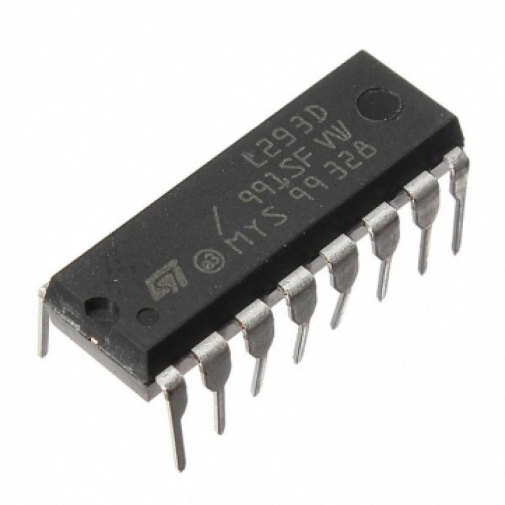
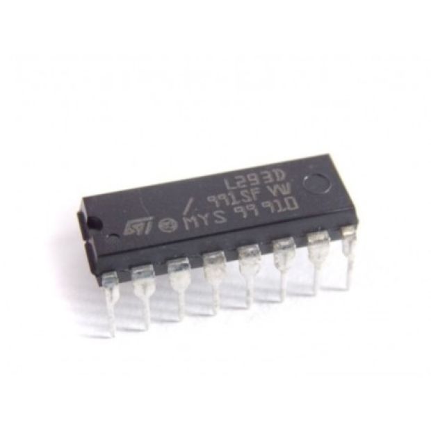
L293D IC
L293D is a basic motor driver integrated chip (IC) that enables us to drive a DC motor in either direction and also control the speed of the motor. The L293D is a 16 pin IC, with 8 pins on each side, allowing us to control the motor. It means that we can use a single L293D to run up to two DC motors.
₹ 36 ₹69
69
Seller Electro Boat


No FAQs Found
0 Reviews For this Product
Related Products


2.jpeg&width=225&quality=80)
2.jpeg&width=225&quality=80)
.jpeg&width=225&quality=80)

