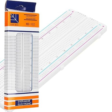


Breadboard MB 102 840 Point (Large) Experimental Solderless Board
Description: It has 2 power buses, 30 columns, and 10 rows - a total of 400 tie in points. All pins are spaced by a standard 0.1". The two sets of five rows are separated by about 0.3", perfect for straddling a DIP package over.
₹ 57 ₹99
99


| Made In : | India |
Add FAQ
A breadboard is a solderless prototyping board designed for easy and quick assembly of electronic circuits without the need for soldering. Ideal for DIY electronics projects, circuit design, and prototyping, a breadboard allows you to connect components such as resistors, capacitors, and ICs using jumper wires and connectors. It is an essential tool for engineers, hobbyists, and students working on projects like Arduino circuits, Raspberry Pi experiments, or any other electronics-related tasks.
This breadboard provides a versatile, reusable platform that makes testing and modifying circuits hassle-free. With its grid of interconnected holes, users can easily create temporary circuits to test ideas before finalizing their designs. Available in various sizes and configurations, breadboards are perfect for small and medium-sized electronic projects. Whether you're creating a sensor circuit, a power supply, or a simple LED light project, a solderless breadboard is a must-have item in any electronics toolkit.
Key Features:
- No soldering required for quick circuit assembly
- Ideal for Arduino projects, Raspberry Pi setups, and more
- Compatible with standard electronic components
- Reusable, making it cost-effective for multiple projects
- Available in a variety of sizes to suit different project need
A medium breadboard is a versatile tool used in electronics prototyping and circuit design. It allows for the easy assembly and testing of electronic circuits without the need for soldering. Here’s a detailed description of a medium breadboard, including its features, layout, and usage:
Key Features:
-
Size and Layout:
- Dimensions: A medium breadboard typically measures around 170-200 mm in length and 50-70 mm in width.
- Grid Pattern: The breadboard is marked with a grid of holes arranged in rows and columns, allowing for easy insertion and connections of electronic components.
-
Structure:
- Rows and Columns: The breadboard consists of multiple rows and columns of holes that are electrically connected internally. These are usually divided into:
- Bus Strips: Long horizontal rows along the top and bottom edges of the breadboard, used for power distribution. Each strip is usually split into two, one for the positive voltage and one for the ground.
- Terminal Strips: The central area of the breadboard where components are placed. It is divided into two sections, each containing several rows of interconnected holes.
- Rows and Columns: The breadboard consists of multiple rows and columns of holes that are electrically connected internally. These are usually divided into:
-
Connection Points:
- Terminal Strip Rows: The terminal strips have rows of holes where components can be inserted. Each row is electrically connected internally, making it easy to build circuits by connecting components in a row.
- Bus Strips: The bus strips along the edges provide a convenient way to distribute power to various parts of the circuit. They are usually connected in columns along their length but not across the central divide.
-
Material and Build:
- Plastic Base: Made from durable plastic with a grid of holes that are usually designed to hold standard-sized components.
- Metal Clips: Underneath the breadboard, metal clips or conductive strips connect the rows of holes, allowing for easy electrical connections.
Usage:
-
Component Placement:
- Components such as resistors, capacitors, ICs, and connectors can be inserted into the breadboard. The flexible arrangement allows for easy modification and experimentation with different circuit designs.
-
Circuit Prototyping:
- Building Circuits: Components are connected by inserting their leads into the holes. The internal connections allow components to be interconnected without the need for soldering.
- Testing and Debugging: Breadboards are ideal for testing and debugging circuits before committing to a permanent soldered design. They allow for easy reconfiguration and adjustments.
-
Power Distribution:
- Power Supply: Power is supplied through the bus strips, which can be connected to a power source (e.g., a battery or power supply unit). The bus strips distribute power to the rest of the circuit, making it easy to power multiple components.
-
Educational and Experimental Use:
- Learning Tool: Breadboards are widely used in educational settings to teach and learn about electronics. They provide a hands-on way to understand circuit concepts and components.
- Prototyping: Engineers and hobbyists use breadboards to prototype and test circuit designs before creating printed circuit boards (PCBs) or finalizing designs.

0 Reviews For this Product


1.jpeg&width=225&quality=80)


4.jpeg&width=225&quality=80)

