
_2.jpg)
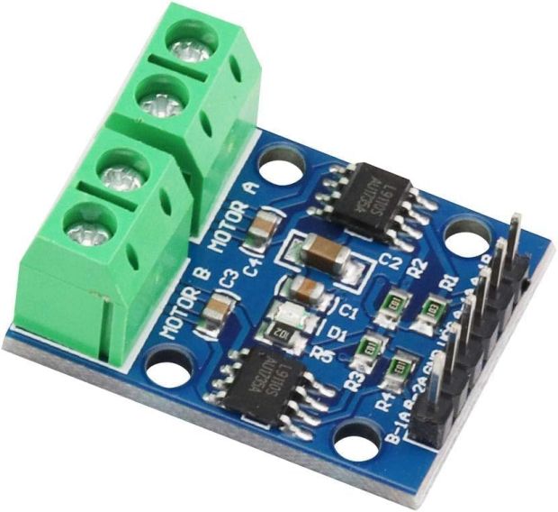
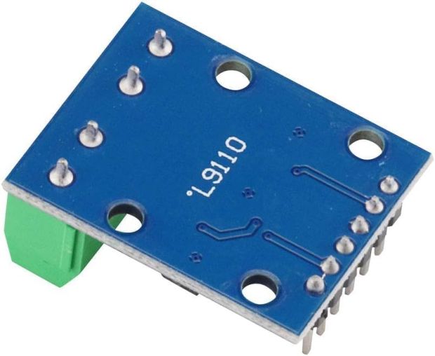
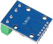
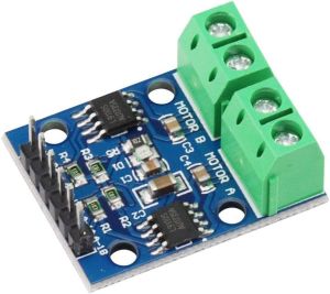
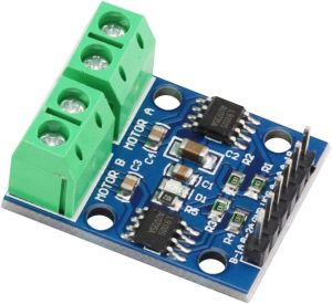
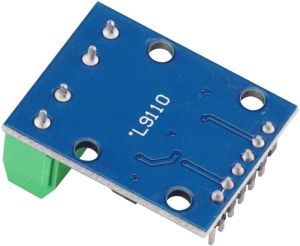
L9110S Dual DC Stepper Motor Driver Module (Normal Quality)
Power miniature robotics and mechatronics projects efficiently with the Electroboat L9110S Dual DC Stepper Motor Driver Module. Powered by dual onboard L9110S H-bridge driver ICs, this compact board controls either two independent bidirectional DC motors or one 4-wire 2-phase stepper motor. Operating across a wide 2.5V to 12V supply range, it integrates smoothly with 3.3V and 5V microcontrollers like Arduino, ESP32, and Raspberry Pi.
₹ 46
₹ 59


The Electroboat L9110S Dual Channel Motor Driver Module is an ultra-compact, cost-effective H-bridge motor driver board designed for small-scale robotics, RC vehicles, and automated mechanism prototypes. Featuring two onboard L9110S monolithic H-bridge ICs, this module delivers up to 800mA of continuous current per channel with built-in output clamp diodes to suppress inductive voltage spikes from DC motors.
The board features TTL/CMOS-compatible logic inputs, allowing direct connections to 3.3V and 5V microcontrollers. Speed regulation is handled easily via Pulse Width Modulation (PWM) on control inputs, while direction is set using basic high/low logic. It includes screw terminal blocks for secure motor connections and male headers for simple breadboard or jumper wire connections.
Key Features and Benefits
-
Dual Channel Control: Independently drives two DC motors or one 4-wire 2-phase bipolar stepper motor.
-
Wide Motor Supply Range (2.5V to 12V): Compatible with standard battery packs, 5V power banks, and 9V/12V DC power adapters.
-
800mA Output Capability: Handles up to 800mA continuous current per channel (1.5A peak capability).
-
Built-In Protection: Integrated output clamping diodes safeguard control logic against back-EMF voltage transients.
-
Microcontroller Ready: Compatible with 3.3V and 5V logic levels (Arduino, ESP32, STM32, Raspberry Pi) without logic level converters.
Technical Specifications
How to Use
-
Power Supply: Connect motor supply voltage (2.5V–12V) to
VCCand system ground toGND. -
Motor Connections: Wire DC Motor A to output terminal 1 (
OA1/OB1) and DC Motor B to output terminal 2 (OA2/OB2). -
Logic Inputs:
-
AIA&AIB: Controls direction and speed (via PWM) for Motor A. -
BIA&BIB: Controls direction and speed (via PWM) for Motor B.
-
-
Control Logic Truth Table:
-
AIA= HIGH,AIB= LOW Motor A Forward -
AIA= LOW,AIB= HIGH Motor A Reverse -
AIA= LOW,AIB= LOW Motor Stop/Brake
-
Applications
-
Small 2WD / 4WD Smart Robot Chassis & Obstacle Avoiding Bots
-
Mini 4-Wire Bipolar Stepper Motor Controllers
-
Pan-Tilt Camera Gimbal Actuators & Smart Lock Mechanisms
-
DIY Automated Toy Cars, Drones, and Conveyor Belts
-
Microcontroller Mechatronics & Educational STEM Projects
Package Includes
-
1 x L9110S Dual DC Stepper Motor Driver Board (Normal Quality)
Shipping & Delivery
-
Free shipping on orders above ₹999 across India.
-
Dispatched within 1-3 business days.
-
Expected delivery: 3-7 business days depending on location.
-
Secure ESD and cushioned packaging to ensure safe transit of electronic components.
0 Reviews For this Product

Related Products