

8-Channel Infrared Line Tracking Sensor Module – IR Detection Trace Sensor Board
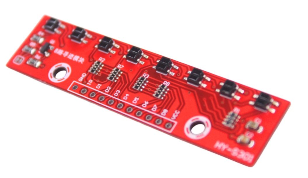
8 Channel Infrared Detection Line Tracking Sensor Module HY-S301 contains 8 IR LED/phototransistor pairs. Each sensor has a separate digital I/O measurable output . This reflection sensor array is designed to be used as a line sensor, but it may also be used as a proximity or reflection sensor. The 8-Channel IR Line Tracking Sensor Module is a high-performance infrared detection board designed for robotic line-following applications. Compatible with Arduino, Raspberry Pi, and other microcontrollers for precise path tracing and obstacle sensing.
₹ 230
₹ 399


| : | |
| Made In : | India |
This sensor array enables smooth and accurate line following by detecting surface reflectivity differences.
Key Features
- 8-channel infrared sensor array
- High sensitivity IR detection system
- Suitable for black line on white surface tracking
- Fast response time for real-time navigation
- Digital output signals for easy interfacing
- Compatible with Arduino and microcontrollers
- Adjustable sensitivity (on some models)
- Ideal for robotics and automation projects
Technical Specifications
| Parameter | Specification |
|---|---|
| Sensor Type | Infrared Reflective Sensor Array |
| Channels | 8 IR sensor pairs |
| Operating Voltage | 3.3V – 5V DC |
| Output Type | Digital (HIGH/LOW) |
| Detection Method | IR reflection (black/white contrast) |
| Response Time | Fast switching |
| Interface | Digital output pins |
| Mounting Type | PCB module |
0 Reviews For this Product
Related Products


