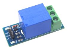

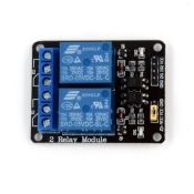
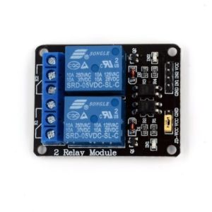
5V 2-Channel Relay Module TTL – Dual Channel Control Board
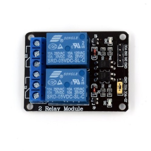
12V 2CH Relay Module is a small and easy to use . Use it to control one 240V power appliance directly from Arduino, Raspberry Pi, and other microcontrollers or low voltage circuits. The 5V 2-Channel Relay Module allows microcontrollers like Arduino, Raspberry Pi, and ESP8266 to control high voltage appliances (AC/DC). This opto-isolated relay board supports 2 independent channels, making it ideal for smart home, industrial, and DIY automation systems.
₹ 63
₹ 129


| : | |
| Made In : | India |
The 5V 2-Channel Relay Module with TTL Input is an essential power switching interface board that bridges low-voltage digital microcontrollers with high-voltage electrical appliances. Each channel is equipped with a high-quality electromagnetic relay rated to switch loads up to at or .
To ensure maximum system safety and stable operation, the board integrates optical isolation (optocouplers) for both channels. This isolates the sensitive digital microcontroller pins ( TTL logic) from high-voltage transients, back-EMF feedback, and electromagnetic interference (EMI) caused by switching inductive loads like AC motors or solenoids.
The module supports both Active-LOW and Active-HIGH trigger configuration options (selectable via onboard jumper on standard models), alongside individual status LEDs that illuminate whenever a relay channel is activated. High-current screw terminal blocks provide secure, solder-free wiring for external AC/DC loads.
Key Features and Benefits
-
Dual Independent Control Channels: Switch two separate AC or DC electrical loads independently using two digital GPIO signals.
-
Optocoupler Signal Isolation: High-speed optocouplers separate logic signals from high-power loads to protect microcontrollers against electrical noise and ground loops.
-
Microcontroller & TTL Compatible: Direct interface with and logic levels from Arduino, ESP32, Raspberry Pi, STM32, and PIC.
-
Visual LED Status Indicators: Red power LED indicates board status, while channel-specific LEDs light up when the respective relay triggers.
-
Heavy-Duty Screw Terminals: Sturdy blue terminal blocks ensure quick, low-resistance connections for heavy wire gauges ().
-
Flexible Power Isolation (JD-VCC Jumper): Removable JD-VCC jumper allows powering relay coils separately from the microcontroller's logic power supply for maximum isolation.
Technical Specifications
Pinout & Wiring Guide
1. Terminal & Header Connections:
2. Typical Wiring Schematic (Arduino Interfacing):
   +-----------------------+                    +-----------------------+
   |      Arduino /        |                    |   5V 2-Channel Relay  |
   |   Microcontroller     |                    |        Module         |
   +-----------------------+                    +-----------------------+
   |  5V Power             |------------------->| VCC                   |
   |  GND                  |------------------->| GND                   |
   |  Digital Pin D2       |------------------->| IN1                   |
   |  Digital Pin D3       |------------------->| IN2                   |
   +-----------------------+                    +-----------------------+

   [EXTERNAL LOAD WIRING - CHANNEL 1]
   AC Mains Live Line ---> COM1 Terminal
   NO1 Terminal       ---> Appliance / Bulb ---> AC Mains Neutral Line
SAFETY WARNING: Working with AC mains voltage () carries severe risk of electric shock. Always disconnect main power sources before touching screw terminals or wiring. Ensure proper insulation and enclosure protection.
Applications
-
Smart Home Automation: Remote control of AC lights, ceiling fans, heaters, and appliances via Wi-Fi or Bluetooth.
-
Industrial Automation: Interfacing PLCs or microcontrollers with solenoid valves, contactors, and pumps.
-
Robotics & Motor Reversing: Switching high-current DC motors or switching direction in H-bridge configurations.
-
Security & Access Control: Triggering door strike solenoids, alarm sirens, and gate actuators.
Package Includes
-
1 x 5V 2-Channel Relay Module with Optocoupler Isolation (TTL Input)
Shipping & Delivery
-
Free shipping on orders above ₹999 across India
-
Dispatched within 1-3 business days
-
Expected delivery: 3-7 business days depending on location
-
Anti-static ESD protective packaging for safe transit
0 Reviews For this Product

Related Products